|
|
|
OPEN EXHAUST, the Detroit Region, SCCA, magazine, September, 1960
|
|
|
VIOLENT LOTUS-VALIANT by Floyd Lawrence |
|
| A chassis engineer might
be defined as a man concerned with translating the output of a power
train into the most effective motion.
On that basis, a chassis man would expect of a power train above all things else the ability to keep delivering output for the chassis to do things with. And such, highly over-simplified, is the concept behind the Lotus-Valiant. This car is the product not of one chassis engineer, but of five . . . Trant Jarman, Russ Shreve, George Wallace, Chris Kennedy and Dave Long. As scholars of chassis performance, their mental exercise led them into a consideration of what the ideal sports-racing car might be like. Among several designs they developed for various classes, there was a 3-litre car that especially took their fancy which utilized the 2770 cc Valiant engine, Corvette four-speed gearbox and Valiant rear end. Gene Casaroll of Dual Ghia fame liked the design and agreed to sponsor the car. At this time two factors entered the picture: Time was too short to build a car from scratch for the 1960 racing season and a Lotus XI LeMans became available. Although the car went closer to the chassis stress limits at some points than their theoretical design, analysis revealed that it was otherwise virtually what they had designed starting from a blank sheet of paper. Size, weight, wheelbase . . . the entire package fitted. After buying the car, and before removing the Stage Three 1100 cc Climax engine, they spent two weeks carefully weighing and measuring to assess exactly what they were starting with. This gave them a standard against which to evaluate any future modifications which might be made in progressing toward their theoretically determined concept. Satisfied that they knew what they had from an engineering standpoint and knowing what they wished to achieve, it was then possible to evolve a procedure of the steps necessary to reach the goal and this was done next before any work actually began. Working in Russ Shreve's garage and using ordinary hand tools, the group removed all of the center portion of the original frame from the rear cockpit structure forward with the exception of the driver's foot box. Each drive-line unit and chassis member was carefully weighed as it was removed, the resulting change in the vehicle being evaluated as regarding strength and weight distribution. |
|
  |
|
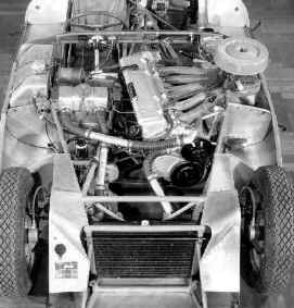
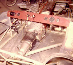
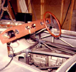
| Next a gutted engine,
transmission and differential were fitted into approximate position for
mock-up. A rather remarkable drive shaft only 2-1/8th inches long
was designed to join the transmission U-joint to the U-joint of the
differential and the layout of the structural members was begun.
The layout of the driveline having been established by the known weights related to the design concept, it was now necessary to design a structure to support the units without the benefit of the cross-member which, in its former location, would pass directly through the engine block. In solving this problem, perhaps the most unusual design feature of the car was created after many nights of group discussion. Starting with the triangulated and rigid rear structure, the five laid out a box-section extending forward to the aluminum adaptor plate by which the transmission was mounted to the bell housing. Mocked up with strings, the structure clearly would act like a backbone for the chassis and provide excellent torsional rigidity for the engine. The engine, however, hanging forward from the adapter support obviously lacked beam stiffness. At the same time, the frame members from the cockpit forward had excellent beam stiffness but without cross members lacked torsional rigidity. Each had what the other lacked, in short, but mounting the engine to serve this function in the chassis was a new concept so far as the group knows. It was done and it works. The engine is joined to the frame in such a way that it becomes a member lending torsional rigidity and receiving beam stiffness from the frame in turn. Moreover, this was done utilizing the original mount of the Valiant engine with a suitably triangulated attachment as shown. With the engine becoming part of the frame, it was necessary to use the car as a jig for engine installation with each member aligned and welded into place on the spot. The adaptor plate being a structural member as well, four reamed holes are utilized to give the engine precise location and rigidity. Moreover, the jigging system of construction required a precise assembly sequence since the location of each member depended on the location of the members preceding it All of this had to be programmed, checked, double-checked and carried out with precision. One other drive-line feature which might be mentioned at this point is the quick change differential. . .in this instance literally the differential being changed. A mounting plate was designed and constructed to which are attached both the caliper disc brakes and the differential. Four bolts loosen the Girling brakes which can be dropped back on rubber lines without disconnection. Three bolts free the differential housing which is then disconnected from the half shafts and the U-joint. The three Valiant ratios . . . 3.91, 3.23 and 3.55 . . . are carried completely assembled and filled with oil ready to change as described in just 45 minutes. |
|
|
|
|
| As finally completed,
the Valiant engine is mounted in the car at the standard 30 degrees off
the vertical and is at an angle of 6-1/2 degrees to the centerline of
the car. Power output of the Hyperpak unit is estimated by the
group at 185 hp with a vehicle weight of 1370 lbs. including oil, water
and three gallons of gas.
Previously the car had weighed 980 lbs. in similar condition with a comparative rating of 85 hp. The former weight distribution was 55 front and 45 rear, a condition which the engineers were successful in reversing precisely in accordance with their previous concept. Right to left weight distribution is 50-50 within 5 lbs. Modifications not previously mentioned include changing the coil spring rate and loaded height to compensate for the added weight and fabricating a radiator of the required cooling capacity within the space available utilizing a deep core. |
|
|
|
|
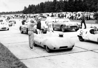
| With a maximum top speed
of 170 mph at 6000 rpm and a drive-line that promises the reliability of
a truck, the car has already shown itself to be a comer. Driven by
Trant Jarman at Green Acres, the car was first in the over 1600 cc
modified event and in the 30 lap feature was first in class and third
over-all behind an RS-60 and a Lola.
But most important of all, in over 200 racing miles the car shows that it is close to what its designers intended . . . a car that always does the proper thing: which will probably include winning often. The website editor wishes to thank Clark Lance for this article, and to Russ Shreve for the original photos. As a footnote, in 1961 the car was shipped to Arizona to Bob Montana. While still in the Phoenix area it was advertised for sale by John Jewett in July of 1965 in Competition Press, with an asking price of $1500. Late in 1966 it was in the San Francisco area, advertised for sale again. The seller, Earl Shuholm, had it listed for the next six months with the price finally lowered to $1100. It was finally sold to a man from Los Angeles who planned to take it to Bonneville. After that the trail on the car seems to fade out. We all ask, where is this car today? For more on the Lotus-Valiant from its creators, click here.
|
|